During the implementation of the RELABEMA project, Vilnius Tech was responsible for the project Output 3. At present, there are not many laboratories in the virtual environment where it is possible to control or simulate real electrical and electronic measuring devices. In addition, the literature analysis did not identify any virtual reality laboratories that could remotely control real equipment in real time.
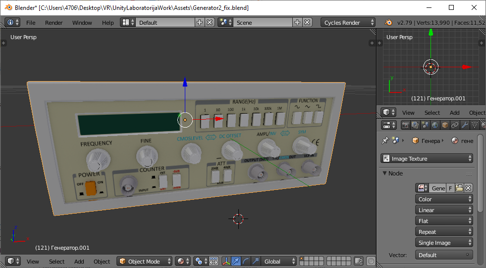
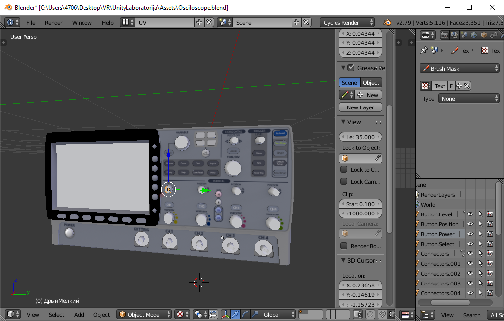
The De Lorenzo company equipment was used. Some of the most widely used devices are signal generators and oscilloscopes, which are also equipped with De Lorenzo equipment. However, it was not virtualized and is not good looking. For this reason, development of typical models of such devices with the help of the „Blender“ software was conducted. At the same time, the entire electrical and electronics laboratory environment of a typical research institution was created, which also will be interactive.
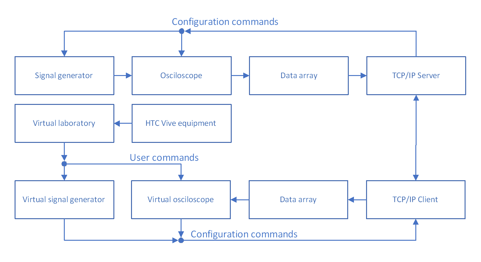
An embedded system with software (microcontroller STM32F4 family and code in the C programming language) was developed that allows live signal generator and oscilloscope data to be transferred to the developed computer software. The computer software transmits the results using the TCP / IP service to the Internet, and also waits for execution commands to change the configuration of the devices in use.
Client part software was also developed. Graphical models of devices were created. Since all of the models have been created, they might be used with the „Unity“ software, which allows to create virtual interactive environments and games. The scripts and interactivity of the virtual laboratory was developed using the C# programming language. C# integrate a TCP / IP client service that can receive and transmit data to a remote management system. All remote monitoring and control of the equipment is realized using „HTC Vive“ trackpads. This equipment allow students to successfully get acquainted with the devices for generating and measuring signals and perform simple laboratory tasks as if it were real equipment to work with.

Fig. 1. Generator model

Fig. 2. Oscilloscope model

Fig. 3. Workflow algorithm of the virtual laboratory
